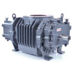
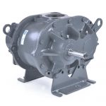
Performance calculations for rotary positive displacement blowers require the use of several equations. These equations are presented below in the calculation order that is most logical. Typical equations are provided for both Roots and Sutorbilt.
Slip represents the amount of gas (air) which leaks back through the very small clearances which are present between the impellers and headplate, the impellers and the cylinder and between the impellers. The slip is the RPM (Revolutions per Minute) required to compensate for this leakage.
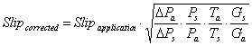
Where:
|
Slipcorrected
|
Slip of the unit at actual operating conditions (RPM)
|
|---|---|
|
Slipapplication
|
Slip of the unit at 1 psi (measured in RPM)
|
|
Δ Pa
|
Differential Pressure in psi
|
|
Δ Ps
|
Standard Pressure rise = 1 psi
|
|
Ps
|
Standard Absolute Pressure in psia
|
|
Pa
|
Actual absolute inlet pressure in psia
|
|
Ta
|
Actual absolute inlet temperature in °R (°F+460)
|
|
Ts
|
Standard absolute inlet temperature in °R, 528°R
|
|
Gs
|
Standard Specific Gravity of air, 1.0
|
|
Ga
|
Actual Specific Gravity of gas
|
Slipapplication is determined by blanking off the discharge of a blower and rotating the blower at the speed that will generate a 1 psi at the discharge. This is also referred to as 1 psi slip.
Ga is determined by dividing the molecular weight of the desired gas by 28.964 which is the molecular weight of dry air.

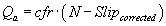
Blower or vacuum pump inlet volume can be calculated with the following equation:
Where:
|
Qa
|
Actual Inlet Volume in cfm
|
|---|---|
|
cfr
|
Cubic Feet per Revolution (displacement)
|
|
N
|
Speed of unit in RPM (revolutions per minute)
|
|
Slipcorrected
|
Slip of the unit at actual operating conditions (RPM)
|
If cfr is not known for a unit, one could estimate it with the following equation:
![]()
Where:
|
GD
|
Gear Diameter in inches |
|---|---|
|
CL
|
Cylinder Length in inches |
This calculation for cfr assumes an 80% involute profile design.
The brake horsepower required to drive the blower is calculated with the following equation:
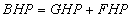
Where:
|
BHP
|
Brake Horsepower |
|---|---|
|
GHP
|
Gas Horsepower |
|
FHP
|
Friction Horsepower |
A quick method to calculate Brake Horsepower to get you in the ball park is to use the following equation:
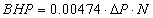
Where:
|
ΔP
|
Differential Pressure between inlet and discharge in psi |
|---|---|
|
N
|
Speed of the unit in RPM |
|
0.00474
|
Represents a constant that includes 7.8% for friction losses |
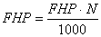
If you want to fine tune your brake horsepower calculation, the Gas Horsepower will be calculated separately from the Friction Horsepower. Gas Horsepower for a conventional rotary positive displacement blower can be calculated with the following equation:

The formula that is used for a Whispair© unit (jet – assisted) is:

Fg must be obtained from a graph that has gear tip speed on the x-axis and Fg on the y-axis. This curve is specific for a particular series of units or a specific unit and is typically proprietary for the blower manufacturer.
Friction Horsepower can be calculated using several different strategies. All strategies require a Friction Horsepower provided by the manufacturer. This friction horsepower is typically based on either Friction Horsepower per 1000 RPM or Friction Horsepower at the maximum RPM which in turn can be related to gear tip speed.
Friction Horsepower per 1000 RPM can be defined as follows:
Friction horsepower defined by the maximum friction horsepower at the maximum speed is:
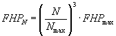
FHP/1000, FHPN, FHPmax, and Nmax are supplied by the manufacturer.
Gear tip speed in fpm (feet per minute)can be calculated with the following equation:

|
GD
|
Gear Diameter in inches |
|---|---|
|
N
|
Speed of shaft in RPM |
We can now calculate temperature rise on the unit. Temperature rise is a critical calculation since the blower has limits on thermal growth. To much temperature rise and the impellers will expand into the headplates causing the unit to seize and possibly causing extensive damage to the unit.
Two formulas can be used. The first formula is only applicable to air and is as follows:
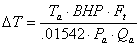
The following formula can be used for any gas:
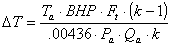
| Ta | Actual absolute inlet temperature in °R (°F+460) |
|---|---|
| BHP | Brake Horsepower |
| Ft | Temperature rise factor from manufacturers table |
| k | Ratio of specific heats for a gas cp/cv |
| Pa | Actual absolute inlet pressure in psia |
| Qa | Actual Inlet Volume in cfm |
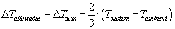
Temperature rise exerts a couple additional limitations on rotary positive displacement blowers. Most manufactures impose an average temperature rule as well as a reduction in maximum allowable temperature rise when inlet gas temperatures exceed ambient conditions.
These two rules can be expressed mathematically as follows:
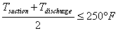
|
Tsuction
|
Inlet Temperature in °F at blower inlet |
|---|---|
|
Tdischarge
|
Discharge Temperature in °F at blower discharge |
|
ΔTallowable
|
Revised maximum allowable temperature rise |
|
ΔTmax
|
Manufacturers maximum allowable temperature rise |
|
Tambient
|
Ambient Temperature around the blower in °F |
If you want a printable version of this article, please click here.